2000B Thermal Conductivity Gas Analyser in Explosion-Proof Housing, Sealed Reference
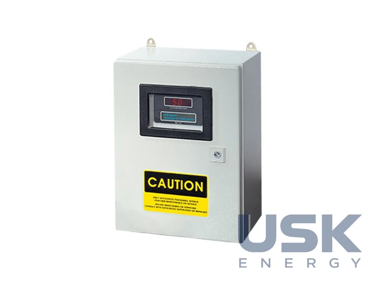
The 2000B thermal conductivity analyser uses a sealed air reference and is housed in a VE series enclosure for Class I, Div 1, Groups B, C & D hazardous areas. It measures the concentration of a component in a gas mixture and provides analogue outputs, alarm contacts and an RS-232 port.
- Measuring principle
- thermal conductivity, comparison with reference gas
- Reference
- sealed air
- Housing
- VE series, Class I, Div 1, Groups B, C & D
- Power
- 115/230 V AC, 50/60 Hz
Price, availability and lead time on request. We help with analogue selection, customs clearance and delivery.
Description
The 2000B determines the content of a target gas or the purity of a stream by comparing the thermal conductivity of the sample with that of a reference gas of known composition. In the 2000B the reference is sealed air, so no separate reference gas feed is needed. The analyser belongs to the 2000 series and uses the same measuring circuit as the panel models: a standard TC cell with a four-filament detector, a nickel-plated brass block, nickel alloy filaments, and stainless steel tubing and end plates.
The electronics sit in a VE series enclosure approved for Class I, Div 1, Groups B, C & D. Power is 115/230 V AC, 50/60 Hz. Cables enter through PG21 and PG29 glands, the PG21 taking cable up to 17 mm and the PG29 up to 26 mm. The terminal block carries the alarm output, range identification contacts, analogue outputs, a calibration contact, solenoid return, the RS-232 port, and connections for a remote sensor and the network.
The gas section has four 1/4-inch tube fittings: sample inlet, zero gas inlet, calibration gas inlet and vent. Zero and span calibration can therefore be carried out through solenoid valves without disconnecting the lines.
The measuring part has three user ranges plus a calibration range, with auto-ranging. Accuracy is ±1% FS for most binary mixtures at constant temperature and ±5% FS over the operating range once stable, and the response is 90% in under 10 seconds at 100 sccm. The operating temperature is 0 to 50 °C, the sample pressure 5 to 50 psig, and the recommended flow 0.1 to 0.4 SCFH. Zero and span drift is ±1% FS. Outputs are two 0 to 1 V DC and two isolated 4 to 20 mA signals, with loads up to 1000 Ohm, plus two programmable set points on 3 A Form C contacts and a system failure contact. Wetted parts are stainless steel, nickel and gold, and NACE-compliant parts are available as an option. The unit carries EAR99 export classification.
Technical specifications
| Measuring principle | thermal conductivity, comparison with reference gas |
|---|---|
| Reference | sealed air |
| Housing | VE series, Class I, Div 1, Groups B, C & D |
| Power | 115/230 V AC, 50/60 Hz |
| Cable glands | PG21 (cable up to 17 mm), PG29 (cable up to 26 mm) |
| Gas connections | sample, zero, calibration gas and vent: 1/4-inch tube fittings |
| Sensor | standard TC cell, four-filament detector |
| Ranges | 3 user ranges plus calibration range, auto-ranging |
| Accuracy | ±1% FS at constant temperature; ±5% FS over operating temperature range |
| Response time | 90% in under 10 s |
| Operating temperature | 0–50 °C |
| Sample pressure | 5–50 psig |
| Analogue outputs | 2 × 0–1 V DC; 2 × 4–20 mA isolated |
| Alarms | 2 set points, Form C 3 A contacts; system failure contact |
| Interface | RS-232 |
| Export classification | EAR99 |
Part numbers
Show all part numbers (1)
2000B
Request a price and lead time
2000B Thermal Conductivity Gas Analyser in Explosion-Proof Housing, Sealed Reference. We reply within one business day.
Or email sales@usk.ua or call 044 339-50-20.
Questions and answers
How does the 2000B differ from the 2000A?
The 2000B is housed for Class I, Div 1, Groups B, C & D hazardous areas and has a sealed air reference. The 2000A is designed for panel mounting in general purpose areas.
What is the supply voltage of the 2000B?
According to the outline drawing, the supply is 115/230 V AC, 50/60 Hz, with the cable entering through a PG21 gland.
How are the gas lines connected?
Four 1/4-inch tube fittings serve as sample inlet, zero gas inlet, calibration gas inlet and vent.
Similar equipment from other manufacturers