IKI-50 (1F R2, 1F/2F R2e) universal fault indicators and feeder controllers for digital MV substations
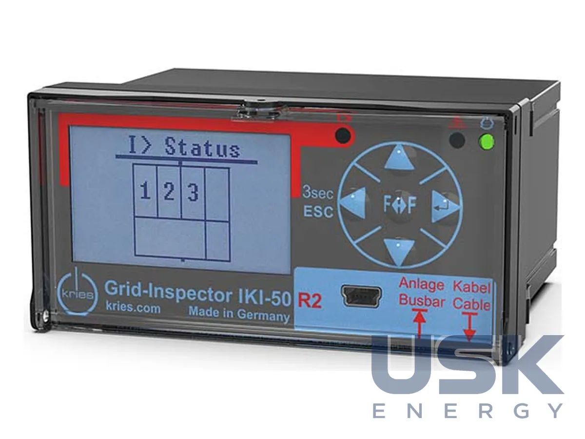
IKI-50 are universal fault indicators and feeder controllers for intelligent medium-voltage distribution substations. They detect directional short circuits and earth faults with a short-circuit setting of 100–1000 A and show data locally and at the control centre. The 1F R2 version controls two motor drives.
- Feeders
- 1 (1F) or 2 (2F)
- Fault detection
- directional short circuit and earth fault, wattmetric and transient methods, pulse location; any neutral treatment
- Short-circuit setting I>>
- 100–1000 A (in steps)
- Measurement
- voltages, currents, power, frequency, cos φ; instantaneous and averaged values
Price, availability and lead time on request. We help with analogue selection, customs clearance and delivery.
Description
IKI-50 (Grid-Inspector) are universal fault indicators and feeder controllers for intelligent medium-voltage distribution substations. Network companies obtain high network transparency at moderate cost. Information on faults, load profiles and setpoint violations is available both locally and at the central control centre, so a fault can be detected and localized immediately.
Fault detection. The devices have all the algorithms for selective detection: directional short circuit and earth fault, static (wattmetric) and transient (wiper) earth fault, pulse location of earth faults. They are suitable for any neutral treatment, and a cable current transformer is not needed. Early fault detection is based on transient disturbances. The partial discharge trend is built by the device together with CAPDIS-S2_55 (R5), with integration over 24 h and a trend over 72 h. The short-circuit setting is 100–1000 A.
Measurement and automation. Voltages, currents, power, frequency and cos φ are measured, as instantaneous and averaged values, and limit values are monitored. Freely programmable logic (up to 32 rules) in the configuration software makes it possible to implement network automation functions. The device is maintenance-free. There is no battery, data are stored indefinitely, and the fault indication remains after loss of supply for more than 6 hours thanks to a capacitor buffer.
Versions. IKI-50_1F R2e and IKI-50_2F R2e are indicators for one or two feeders with one voltage input (LRM/CAPDIS), 4 digital inputs and 4 outputs. IKI-50_2F R2e 1 % has two voltage inputs for resistive sensors with a measurement error of not more than 1 %. IKI-50_1F R2 is a feeder controller. Bus control commands are executed for one feeder with 1.5-pole switching safety; the device controls two motor drives of load-break switches, has 6 relays, 6 digital inputs, two voltage inputs (capacitive and precision 3.25 V/√3) and patented voltage calibration against the reference measurement of another feeder. Communication Modbus-RTU (master/slave) and mini-USB, supply 24–230 V AC/DC, panel-mount housing 49 × 96 × 108 mm, IP54 (front), −25…+55 °C.
Technical specifications
| Feeders | 1 (1F) or 2 (2F) |
|---|---|
| Fault detection | directional short circuit and earth fault, wattmetric and transient methods, pulse location; any neutral treatment |
| Short-circuit setting I>> | 100–1000 A (in steps) |
| Measurement | voltages, currents, power, frequency, cos φ; instantaneous and averaged values |
| Logic | 32 programmable logic rules (configuration software) |
| Control (1F R2) | up to two load-break switches, 1.5-pole switching |
| Voltage inputs | R2e – 1 (LRM/CAPDIS); 1F R2 – 2 (LRM/CAPDIS and precision 3.25 V); 2F R2e 1 % – for resistive sensors, error 1 % |
| Communication | Modbus-RTU, mini-USB |
| Power supply | 24–230 V AC/DC ± 15 %; capacitor buffer for 6 h, no battery |
| Housing | 49 × 96 × 108 mm, cut-out 45 × 92 mm, IP54 (front) |
Request a price and lead time
IKI-50 (1F R2, 1F/2F R2e) universal fault indicators and feeder controllers for digital MV substations. We reply within one business day.
Or email sales@usk.ua or call 044 339-50-20.
Questions and answers
What earth fault detection methods does IKI-50 support?
Static (wattmetric) and transient (wiper) methods and pulse location. The device is suitable for any neutral treatment, and a cable CT is not needed.
How do the 1F R2, 1F R2e and 2F R2e versions differ?
The R2e are indicators for one (1F) or two (2F) feeders with 4 digital inputs and 4 outputs. The 1F R2 is a controller that controls two motor drives, with 6 relays and 6 digital inputs.
What supply and housing does the device have?
Supply 24–230 V AC/DC ± 15 %, no battery, a capacitor buffer holds the indication for more than 6 hours. Panel-mount housing 49 × 96 × 108 mm, IP54 at the front.
Similar equipment from other manufacturers