IKI-23 universal directional fault and load indicator for MV ring main units (including with CAPDIS_top)
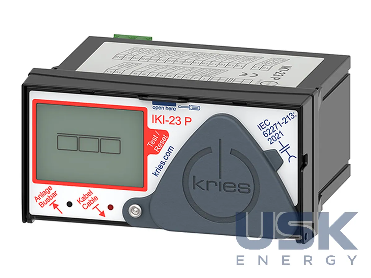
IKI-23 is a directional fault and load indicator for typical medium-voltage ring main units. It determines the direction of short circuits and earth faults in networks with any neutral treatment, without auxiliary power and without a cable current transformer. Housing 50 × 98 × 97 mm, IP54 at the front.
- Fault detection
- directional short circuit and earth fault, static (wattmetric) and transient earth fault, pulse location
- Short-circuit settings I>>
- 100–2000 A; 40–200 ms
- Earth fault settings Ie>>
- 40, 80, 100, 200 A
- Static earth fault Ie>
- 5–30 A
Price, availability and lead time on request. We help with analogue selection, customs clearance and delivery.
Description
IKI-23 combines in one device all the functions of the IKI-2x series and proven fault detection algorithms for networks of any type. No auxiliary power is needed for fault detection, so the device is installed in distribution substations both with and without a connection to telecontrol. The main purpose is medium-voltage ring main units (RMU).
After connection of a capacitive divider or CAPDIS-Sx, the device determines the direction of short circuits and earth faults, of static earth faults (wattmetric method) and of transient earth faults (wiper method). Earth fault detection by pulse location works separately. The neutral treatment can be of any type, and a cable current transformer is not needed. The short-circuit settings are 100–2000 A for 40–200 ms, earth fault 40–200 A, static earth fault 5–30 A.
Built-in diagnostics clearly show the phase sequence, which is used to check that the transformers are connected correctly. Faults are noticed earlier from transient processes, and in the version with Modbus the device keeps a partial discharge trend together with CAPDIS-S2_55 (R5). The event log records the time elapsed since the moment of the fault and is read through the parameterization software and via Modbus. Step voltage monitoring is performed continuously. The device measures the potential difference between the RMU earth and a second earthed point and warns of dangerous voltage, for example during an earth fault, as well as of insufficient earthing of the substation. A three-phase LRM point for expansion modules, phase comparison and CAP-Phase can be added as an option.
Versions: IKI-23 (basic), IKI-23_M with Modbus-RTU and transmission of load values (with IKI-LUM transformers), IKI-23 P with a capacitor communication buffer for Modbus for connecting old substations to telecontrol, IKI-23_CAPDIS_top with a plug-in CAPDIS_top voltage indicator (1–52 kV, IEC 61243-5) in one housing for a 45 × 92 mm cut-out. The indicator checks the absence of voltage under IEC 62271-213:2021 with three-phase continuous indication and a battery-free self-test. Suitable current transformers are of types IKI-LUG and IKI-LUM, and load values are transmitted via Modbus only with IKI-LUM.
Basic settings are made with DIP switches behind the service cover, and full parameterization is done via USB. Housing 50 × 98 × 97 mm, IP54 at the front, operating temperature −25…+55 °C, 4 relays. Existing IKI-22 units are replaced with IKI-23 while retaining the IKI-LUG transformers.
Technical specifications
| Fault detection | directional short circuit and earth fault, static (wattmetric) and transient earth fault, pulse location |
|---|---|
| Short-circuit settings I>> | 100–2000 A; 40–200 ms |
| Earth fault settings Ie>> | 40, 80, 100, 200 A |
| Static earth fault Ie> | 5–30 A |
| Power supply | no auxiliary power for fault detection; 24–230 V AC/DC ± 15 % for Modbus; battery buffer |
| Outputs/communication | 4 relays; Modbus-RTU slave (M version); mini-USB |
| Housing | 50 × 98 × 97 mm, cut-out 45 × 92 mm, IP54 (front) |
| Temperature | −25 … +55 °C |
| Versions | IKI-23, IKI-23_M, IKI-23 P (capacitor Modbus buffer), IKI-23_CAPDIS_top |
Request a price and lead time
IKI-23 universal directional fault and load indicator for MV ring main units (including with CAPDIS_top). We reply within one business day.
Or email sales@usk.ua or call 044 339-50-20.
Questions and answers
What trip settings does IKI-23 offer?
For short circuits 100–2000 A for 40–200 ms, for earth faults 40–200 A, for static earth faults 5–30 A.
Is auxiliary power or a cable current transformer required?
No auxiliary power is needed for fault detection, and neither is a cable current transformer. A 24–230 V AC/DC ± 15 % supply is needed for Modbus communication.
What versions of IKI-23 are available?
IKI-23 basic, IKI-23_M with Modbus-RTU, IKI-23 P with a capacitor Modbus buffer and IKI-23_CAPDIS_top with a voltage indicator in one housing for a 45 × 92 mm cut-out.
Similar equipment from other manufacturers