IKI-22 directional short-circuit and earth fault indicator for MV networks with any neutral treatment
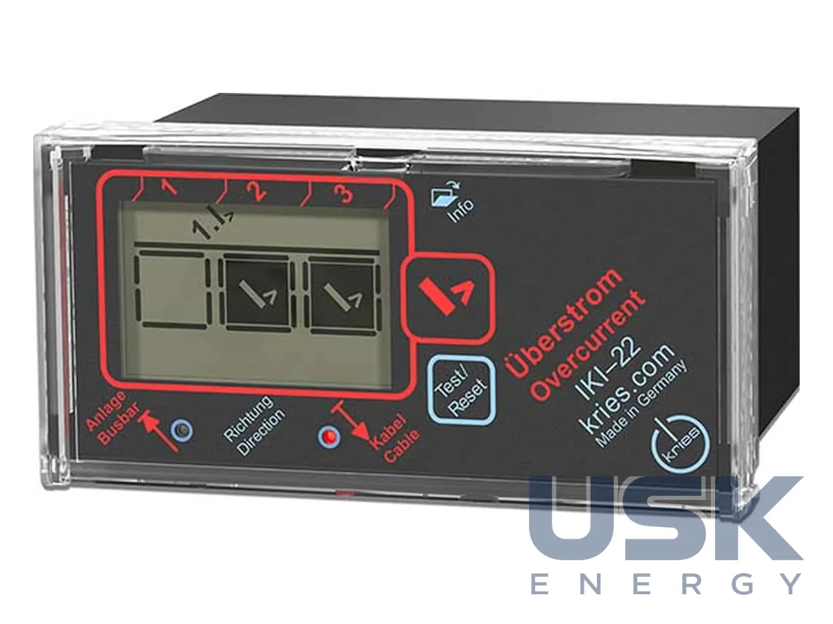
IKI-22 is a combined short-circuit and earth fault indicator with direction detection for medium-voltage cable networks. It works with and without auxiliary power and is suitable for isolated, compensated, low-resistance and short-time low-resistance neutral. Housing 48 × 96 × 80 mm, IP40.
- Neutral treatment
- isolated, compensated, low-resistance, short-time low-resistance
- Short-circuit settings I>>
- 100–2000 A; 40, 80, 150, 200 ms
- Earth fault settings Ie>>
- 40, 80, 100, 200 A; 60, 80, 150, 200 ms
- Transient earth fault
- 3I0 100, 200, 300, 500 A; 3U0 20 or 50 %
Price, availability and lead time on request. We help with analogue selection, customs clearance and delivery.
Description
IKI-22 detects, indicates and signals by telecontrol short circuits and earth faults with the indication of direction, towards the cable or towards the busbars. The device is suitable for all neutral earthing modes, namely isolated, compensated (with an arc suppression coil), low-resistance and short-time low-resistance. Auxiliary power can be supplied, but the device can also do without it.
IKI-22 receives the voltage signals for direction detection from the built-in CAPDIS or CAPDIS-PI voltage indicator through a 0.4 m Y-cable, so separate voltage transformers are not needed. In compensated and isolated networks, the direction of an earth fault is determined by the transient (wiper) method. The zero-sequence signal is calculated from three phase current sensors, a separate cable current transformer is not needed, and there is less installation work. In networks with earthed neutral, short circuits and earth faults are detected without auxiliary power. For directional detection of earth faults by the transient method in compensated and isolated networks, an auxiliary voltage of 24…230 V AC/DC is required.
Operation and indication follow the IKI-20 family pattern. The LCD shows the type of fault per phase, for networks with auto-reclosing the first and second faults are distinguished, and two separate LEDs show the direction. Parameters are set with DIP switches behind the front cover. The test/reset button is used for testing and for resetting the indication. The IKI-22_PF version has potential-free bistable contacts when auxiliary power is supplied, otherwise the outputs work as monostable pulse outputs. There are 4 contacts in total.
Settings: short circuit 100–2000 A for 40–200 ms, earth fault 40–200 A for 60–200 ms, transient earth fault 3I0 100–500 A at 3U0 of 20 or 50 %. Housing 48 × 96 × 80 mm, cut-out 45 × 92 mm, IP40, operating temperature −25…+55 °C. The current sensors are split-core, types IKI-LUG_1500 and IKI-LUM_d92 for a 92 mm diameter. Cable sets of 3.0 and 5.0 m length are offered for connection. Installed IKI-22 units can be replaced with IKI-23 while retaining the IKI-LUG current transformers.
Technical specifications
| Neutral treatment | isolated, compensated, low-resistance, short-time low-resistance |
|---|---|
| Short-circuit settings I>> | 100–2000 A; 40, 80, 150, 200 ms |
| Earth fault settings Ie>> | 40, 80, 100, 200 A; 60, 80, 150, 200 ms |
| Transient earth fault | 3I0 100, 200, 300, 500 A; 3U0 20 or 50 % |
| Voltage for direction | from CAPDIS / CAPDIS-PI via Y-cable |
| Supply buffer | battery |
| Housing | 48 × 96 × 80 mm, cut-out 45 × 92 mm, IP40 |
| Temperature | −25 … +55 °C |
Request a price and lead time
IKI-22 directional short-circuit and earth fault indicator for MV networks with any neutral treatment. We reply within one business day.
Or email sales@usk.ua or call 044 339-50-20.
Questions and answers
What networks does IKI-22 work in?
In MV networks with isolated, compensated, low-resistance and short-time low-resistance neutral. The direction of short circuits and earth faults is determined towards the cable or towards the busbars.
What settings are available for short circuits and earth faults?
Short circuit 100–2000 A for 40–200 ms, earth fault 40–200 A for 60–200 ms. For a transient earth fault 3I0 100–500 A at 3U0 of 20 or 50 %.
Where does the device take the voltage for direction detection from?
From the built-in CAPDIS or CAPDIS-PI indicator through a 0.4 m Y-cable. Separate voltage transformers are not needed.
Similar equipment from other manufacturers