BAU+ and BAU-HVCT — bushing and HV CT sensors for insulation and PD monitoring
BAU+ and BAU-HVCT are sensors for online insulation monitoring systems of high-voltage bushings and instrument current transformers. They output signals of unbalance, leakage current, capacitance, loss tangent and partial discharge. BAU+ has IP67 protection and limits its output voltage to below 23 V peak.
- Purpose
- unbalance, leakage current, capacitance, tg δ and partial discharge signals
- Installation point, BAU+
- measuring (or potential) tap of the bushing
- Installation point, BAU-HVCT
- in series with the earthing wire in the HV CT terminal box
- Protection rating, BAU+
- IP67
Price, availability and lead time on request. We help with analogue selection, customs clearance and delivery.
Description
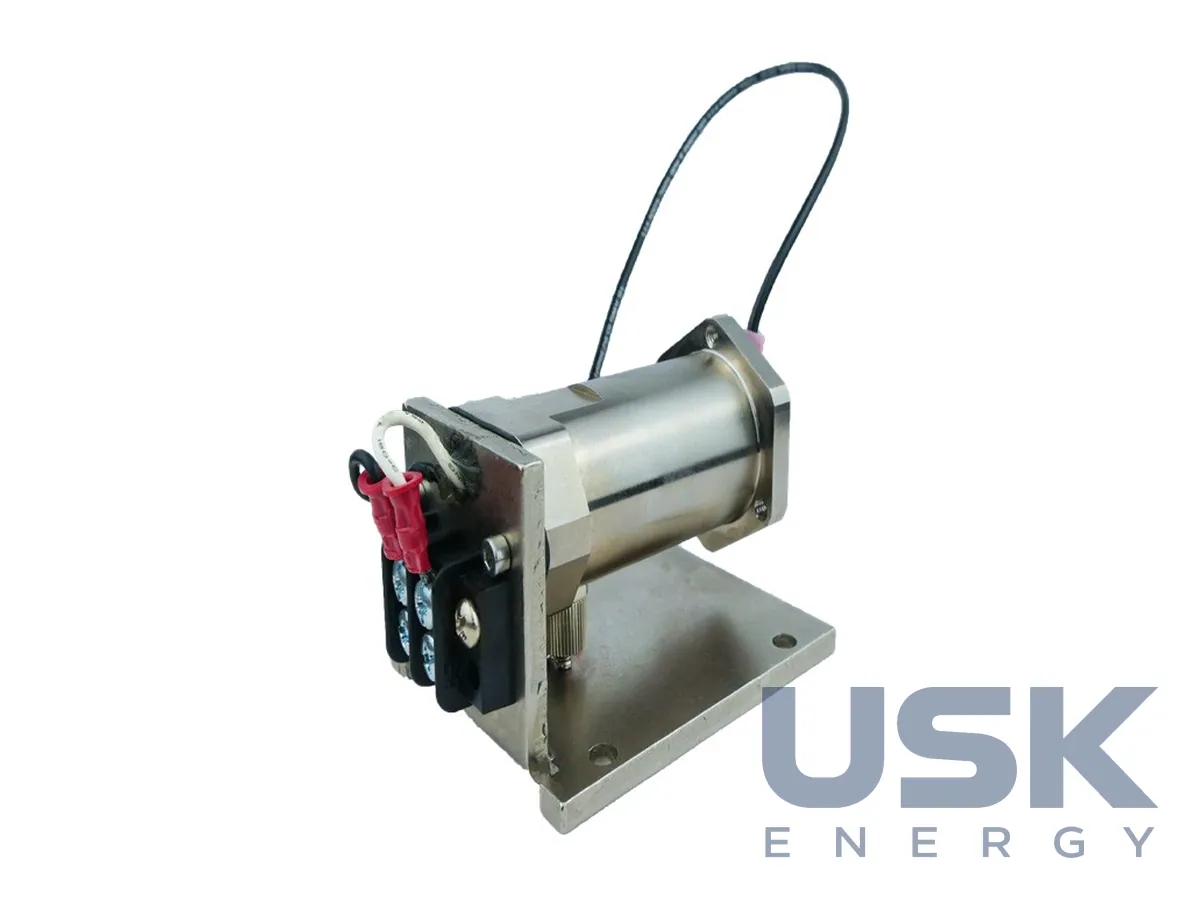
BAU+ (Bushing Adapter Unit) and BAU-HVCT serve as primary transducers for online insulation monitoring systems of high-voltage equipment. The BAU+ is installed on the measuring tap of the bushing and, where there is none, on the potential tap. It outputs signals of unbalance, leakage current, capacitance and loss tangent of the bushing, as well as partial discharge signals from the bushings and the transformer. An additional circuit with a Rogowski coil helps filter interference during PD measurement, so one sensor replaces separate sensors for different tasks. The BAU+ is intended for power transformers, phase-segregated busducts and high-voltage current transformers, and is compatible with the PD modules of monitors and with the manufacturer's portable instruments.
The BAU+ housing has IP67 protection, and three levels of built-in protection are provided. Six voltage limiters with a load-balancing circuit limit the output voltage to below 23 V peak if the connection to the monitoring system is lost. Two circuits protect against switching and system overvoltages. An emergency circuit automatically earths the terminal inside the housing if the other protection levels fail. The sensor consists of a housing, an adapter and a cable connector. The housing is removed after unscrewing three screws, which gives access to the terminal for offline testing. The adapter head and contact are selected to suit the bushing design, while the housing and connector stay the same, and the exact adapter number is determined from the bushing drawing. More than 50 adapters are available for different types of measuring taps.
The BAU+ is supplied with a 50 Ω coaxial cable 25 m long and an angled connector, and for bushings without a turret a straight connector is offered. The version with a preamplifier is designed to work with a Rogowski coil. SS_BAUplus versions come with an armoured coaxial cable, which does not need to be laid in a pipe and simplifies retrofitting at operating substations. Sensors are usually ordered in sets of three.
The BAU-HVCT is a compact sensor for high-voltage current transformers, connected in series with the earthing wire in the CT terminal box. One sensor monitors one CT, and a set of three makes it possible to track loss tangent, capacitance and leakage current and to calculate unbalance. This reveals the typical causes of CT failure: moisture ingress, partial discharges and overfilling with oil at the factory. The output voltage on a broken circuit is limited to below 20 V peak, and overvoltage protection and emergency earthing are provided. The sensor is supplied with flexible leads and a mounting kit, and the coaxial cable is ordered separately. Together with the C50 monitor, the data makes it possible to follow the dynamics of the condition.
Technical specifications
| Purpose | unbalance, leakage current, capacitance, tg δ and partial discharge signals |
|---|---|
| Installation point, BAU+ | measuring (or potential) tap of the bushing |
| Installation point, BAU-HVCT | in series with the earthing wire in the HV CT terminal box |
| Protection rating, BAU+ | IP67 |
| Output voltage limit on open circuit | BAU+ — below 23 V peak; BAU-HVCT — below 20 V peak |
| Protection levels | voltage limiter, 2 overvoltage protection circuits, emergency terminal earthing |
| BAU+ cable | 50 Ω coaxial, 25 m; armoured cable option |
| Versions | BAUplus-xx; BAUplus-xx-A with preamplifier for Rogowski coil; SS_BAUplus (armoured cable); BAU-HVCT-X |
Request a price and lead time
BAU+ and BAU-HVCT — bushing and HV CT sensors for insulation and PD monitoring. We reply within one business day.
Or email sales@usk.ua or call 044 339-50-20.
Questions and answers
Where is the BAU+ sensor installed?
On the measuring tap of the bushing, or on the potential tap where there is none. The housing has IP67 protection, and it is removed after unscrewing three screws for offline tests.
What limits the sensor output voltage if the circuit is broken?
In the BAU+ the output voltage is limited to below 23 V peak, in the BAU-HVCT to below 20 V peak. Two overvoltage protection circuits and emergency earthing of the terminal are also provided.
Which cable is supplied with the sensor?
The BAU+ comes with a 50 Ω coaxial cable 25 m long, and an armoured version is available. For the BAU-HVCT the coaxial cable is ordered separately.
Similar equipment from other manufacturers