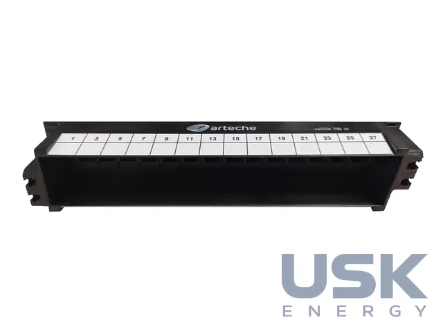
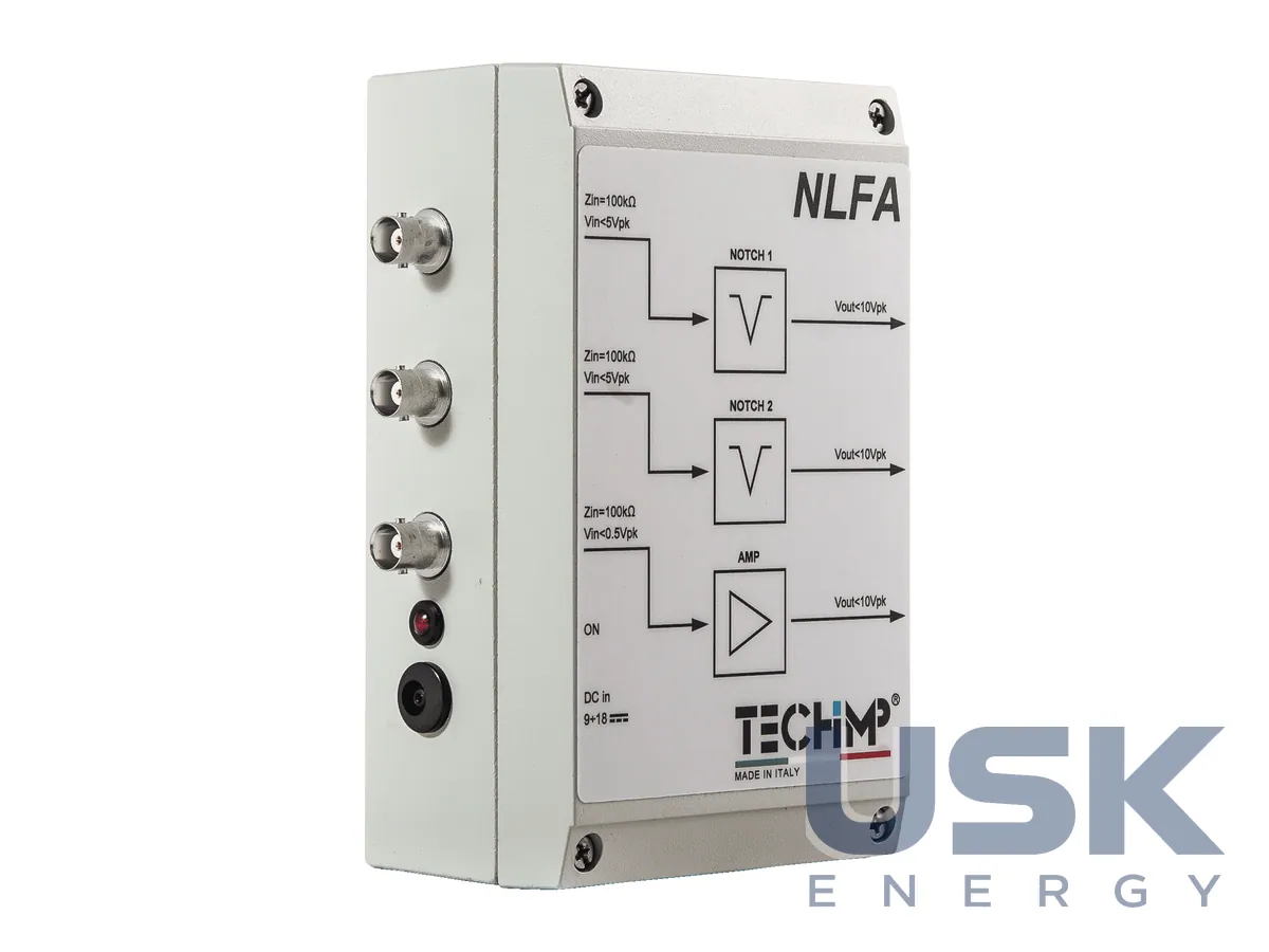
NLFA — notch and low-frequency amplifier to synchronise PD measurement systems
The NLFA contains a low-frequency amplifier and two notch stages tuned to 50 Hz or 60 Hz. It produces a clean synchronisation signal for partial discharge measurement systems during resonant cable tests.
- Composition
- 1 low-frequency amplifier, 2 notch amplifiers
- Bandwidth (-3 dB)
- 1.6 Hz – 9 kHz
- Notch frequency
- 50 Hz ± 0.1 Hz / 60 Hz ± 0.1 Hz
- Attenuation at notch frequency
- Typically above 30 dB
Price, availability and lead time on request. We help with analogue selection, customs clearance and delivery.
Description
The NLFA (Notch Low Frequency Amplifier) is used in resonant tests of medium- and high-voltage cables, where partial discharge measurement systems such as PDSolver, PDBase or PDCheck need a stable synchronisation signal locked to the test voltage phase. Under resonant excitation the frequency and waveform differ from the mains, and feeding the raw signal into the synchronisation input does not always give a correct phase reference for the discharge pattern.
Inside the unit are three independent elements: one low-frequency amplifier and two notch amplifiers with a stopband at 50 Hz, or 60 Hz in a separate version. The elements can be used on their own or combined, and connecting two notch stages in series increases attenuation at the stopband frequency. If both the amplifier and a notch section are needed, the amplifier is placed in front, which lowers its maximum input signal to 0.5 V instead of 1.0 V.
The notch section has a -3 dB bandwidth of 1.6 Hz – 9 kHz, a notch frequency of 50 Hz ± 0.1 Hz or 60 Hz ± 0.1 Hz, and typical attenuation at that frequency above 30 dB. Its input impedance is 100 kOhm and output impedance 10 Ohm, with a transfer ratio of 1 V/V (0 dB) and a maximum voltage of 10 Vpp.
The amplifier section is used when the synchronisation signal from a current transformer, a PQ quadripole or a capacitive divider is too weak to drive the synchronisation input of the PD system directly. It shares the same 1.6 Hz – 9 kHz band, has a gain of 20 V/V (26 dB), accepts up to 1 Vpp and delivers up to 20 Vpp. Its output should drive a high-impedance load above 1 kOhm through coaxial cable up to 30 m long, preferably with double screening.
The NLFA runs from 12 VDC at 500 mA, supplied either by an external power unit or by a standard 12 V battery, which suits fieldwork.
Technical specifications
| Composition | 1 low-frequency amplifier, 2 notch amplifiers |
|---|---|
| Bandwidth (-3 dB) | 1.6 Hz – 9 kHz |
| Notch frequency | 50 Hz ± 0.1 Hz / 60 Hz ± 0.1 Hz |
| Attenuation at notch frequency | Typically above 30 dB |
| Input impedance | 100 kOhm |
| Output impedance | 10 Ohm |
| Notch section gain | 1 V/V (0 dB) |
| Notch section maximum voltage | 10 Vpp |
| Amplifier section gain | 20 V/V (26 dB) |
| Amplifier maximum input | 1 Vpp (0.5 V in cascade with the notch section) |
| Amplifier maximum output | 20 Vpp |
| Load | Above 1 kOhm, coaxial cable up to 30 m |
| Power supply | 12 VDC @ 500 mA, external supply or 12 V battery |
| Application | MV and HV cables, resonant tests |
Request a price and lead time
NLFA — notch and low-frequency amplifier to synchronise PD measurement systems. We reply within one business day.
Or email sales@usk.ua or call 044 339-50-20.
Questions and answers
When is the amplifier section of the NLFA needed?
When the synchronisation signal from a current transformer, a PQ quadripole or a capacitive divider is too weak to drive the PD system input. Its gain is 20 V/V (26 dB).
Why connect two notch stages in series?
Two notch sections in cascade give more attenuation at the 50 Hz or 60 Hz notch frequency than a single section, where it is typically above 30 dB.
What powers the unit in the field?
An external 12 VDC supply or a standard 12 V battery, drawing 500 mA.
Similar equipment from other manufacturers