ITSM synchronisation module for partial discharge measurement under impulse voltage
The ITSM module generates a digital synchronisation signal, so the PDBaseII system can be used for partial discharge testing under impulse voltage. The signal is locked to each voltage impulse from the generator.
- Purpose
- synchronisation of PDBaseII for PD measurement under impulse voltage
- Digital output
- synchronisation signal locked to each impulse of the generator
- Input
- output of the synchronisation sensor, such as a capacitive coupler
- Connection
- DIN channel of PDBaseII
Price, availability and lead time on request. We help with analogue selection, customs clearance and delivery.
Description
The ITSM synchronisation module is used when measuring partial discharge (PD) in insulation that operates under impulse voltage. Typical objects are rotating electrical machines and variable speed drives, where winding insulation is subjected to impulses from a converter. Normal synchronisation to the mains sine wave is unsuitable in this mode, so the PD acquisition system needs a separate reference signal.
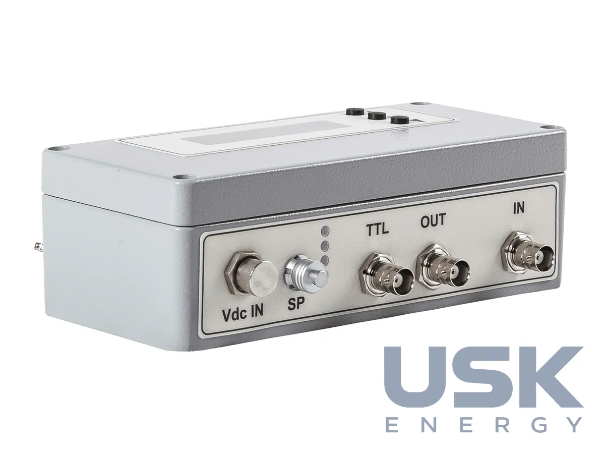
ITSM takes a signal from a synchronisation sensor, such as a capacitive coupler connected to the circuit of the impulse source. From this signal the module forms a digital synchronisation signal tied to each voltage impulse of the generator. The module is connected between the DIN channel of PDBaseII and the output of the synchronisation sensor.
Besides the digital synchronisation signal, ITSM provides a low voltage analogue signal that reproduces the shape of the impulse voltage source. This analogue output can be connected to one of the input channels of PDBaseII, so the synchronisation can be checked and the voltage impulse can be seen together with the PD pulses.
The module needs no separate power supply, since PDBaseII powers it through a grey thin cable with a 5-pin connector. For that reason ITSM is placed close to the measuring unit, and the connections are limited to the synchronisation sensor cable, the power cable and, if needed, the analogue output.
The digital synchronisation signal goes to the DIN channel and the analogue signal to a normal input channel, so one PDBaseII system processes both without separate synchronisation equipment. During set-up, the synchronisation sensor and power cable are connected first, then the analogue output is used to confirm that the synchronisation signal matches the voltage impulse.
Technical specifications
| Purpose | synchronisation of PDBaseII for PD measurement under impulse voltage |
|---|---|
| Digital output | synchronisation signal locked to each impulse of the generator |
| Input | output of the synchronisation sensor, such as a capacitive coupler |
| Connection | DIN channel of PDBaseII |
| Analogue output | low voltage signal reproducing the impulse voltage |
| Power supply | from PDBaseII through a grey thin cable (5-pin) |
| Applications | rotating machines, variable speed drives |
Request a price and lead time
ITSM synchronisation module for partial discharge measurement under impulse voltage. We reply within one business day.
Or email sales@usk.ua or call 044 339-50-20.
Questions and answers
Where is ITSM connected?
Between the DIN channel of PDBaseII and the output of the synchronisation sensor, such as a capacitive coupler. The module forms a digital synchronisation signal from that sensor signal.
Does ITSM need a separate power supply?
No. PDBaseII powers the module through a grey thin cable with a 5-pin connector.
How can the synchronisation be checked?
The analogue output reproduces the impulse voltage and connects to an input channel of PDBaseII, so the impulse can be seen together with the PD pulses.
Similar equipment from other manufacturers