ED3PH — MV current-limiting reactors up to 15.75 kV, up to 2,000 A
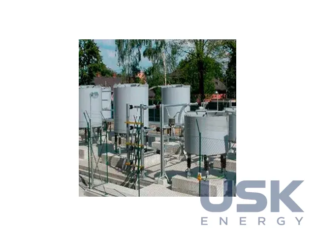
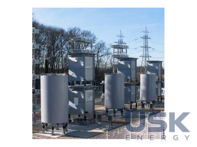
ED3PH air-core current-limiting reactors without a magnetic core are connected in series in the current circuit to limit short-circuit currents. The rated voltage is up to 15.75 kV, the rated current up to 2,000 A, and the reactive voltage drop 2–8 %. They are installed in power supply systems with cogeneration units, in switchgear near large generating units and on MV lines.
- Type
- air-core (coreless) reactor, series connection
- Voltage
- up to 15.75 kV
- Current
- up to 2,000 A
- Reactive voltage drop
- 2–8 %
Price, availability and lead time on request. We help with analogue selection, customs clearance and delivery.
Description
The reactor adds reactance to the circuit, the resulting impedance at the connection point grows, and the short-circuit current falls. In normal operation line current flows through the coils, so the reactor has some power loss and voltage drop. But the lower short-circuit current allows switchgear, cables and apparatus with a lower short-circuit withstand to be chosen. The minimum cable cross-section, selected for thermal withstand, is also reduced.
According to the catalogue card, the reactor works at a frequency of 50 or 60 Hz, has natural air cooling AN, insulation class F (155 °C) or H (180 °C), aluminium or copper windings, stationary installation and protection degree IP00. The design ambient temperature is 40 °C for land use, 45 °C for marine use and from 50 °C for the special version. The reactors comply with PN-EN 60076-6.
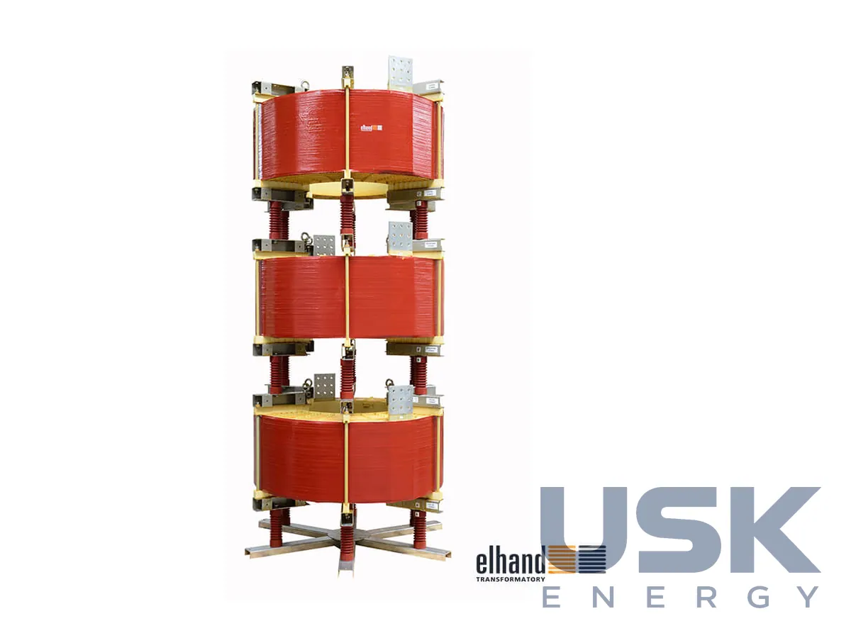
The example in the card has the designation ED3PH-0,35 mH/2000 A 6,3 kV 50 Hz T40F AL. The inductance is 0.35 mH, current 2,000 A, voltage 6.3 kV, voltage drop 6 %. Before the reactor was installed the initial short-circuit current was 76 kA, after it 16 kA, and the permissible peak current is 45 kA (amplitude). Test voltages are LI60/AC20 kV, insulation class F, climatic version C1/E0, duty S1, with aluminium windings and terminals. The dimensions are 1,262 × 2,660 mm, d = 1,232 mm, given in the card as an example.
The selection table in the card contains, for each reactor, the short-circuit voltage of the HV/MV transformer, the short-circuit power and the initial short-circuit current before the reactor is installed, the initial short-circuit current behind the reactor and the peak current behind it. From these values the reactor is calculated for a specific point in the network.
Depending on the available space, the coils of the three phases are mounted one above another or side by side. The reactors stand on post insulators and a special structure. When old 6–10 kV switchgear is reconstructed, such reactors replace concrete and dry-type current-limiting reactors. Versions with parameters outside the card are made by the plant in Poland after prior agreement.
Technical specifications
| Type | air-core (coreless) reactor, series connection |
|---|---|
| Voltage | up to 15.75 kV |
| Current | up to 2,000 A |
| Reactive voltage drop | 2–8 % |
| Frequency | 50/60 Hz |
| Cooling | AN |
| Insulation class | F (155 °C), H (180 °C) |
| Windings | aluminium, copper |
| Example | 0.35 mH, 2,000 A, 6.3 kV, uk 6 %, Isc 76→16 kA, LI60/AC20 kV |
| Standard | PN-EN 60076-6 |
Replacement for
РБ, РБА, РБГ, РБДГ, РТСТ, РТОС (dry-type current-limiting 6–35 kV)
selected by purpose and main parameters, please confirm with our manager
Request a price and lead time
ED3PH — MV current-limiting reactors up to 15.75 kV, up to 2,000 A. We reply within one business day.
Or email sales@usk.ua or call 044 339-50-20.
Questions and answers
By how much does the ED3PH reactor reduce the short-circuit current?
In the catalogue card example, a 0.35 mH reactor for 2,000 A and 6.3 kV with a 6 % voltage drop reduces the initial short-circuit current from 76 to 16 kA. The permissible peak current is 45 kA (amplitude).
What voltage and current is the ED3PH made for?
Rated voltage up to 15.75 kV, rated current up to 2,000 A, reactive voltage drop 2–8 %, frequency 50 or 60 Hz.
Where are the ED3PH current-limiting reactors used?
In power supply systems with cogeneration units, in switchgear near large generating units and on MV lines. The phase coils are placed one above another or side by side.
Similar equipment from other manufacturers