092 Paddle Flow Indicator for Transformer Cooling Systems
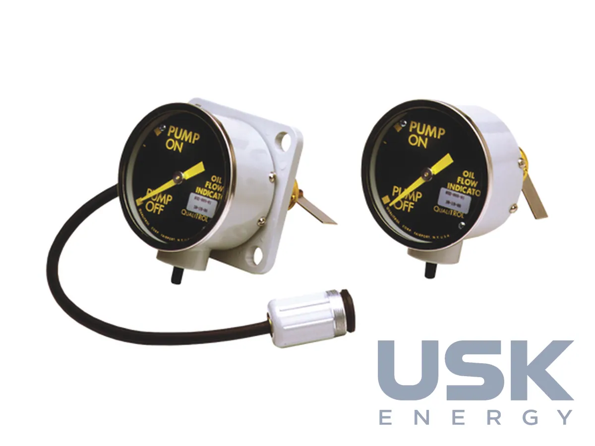
The 092 is a mechanical flow indicator for forced oil or water cooling systems on transformers. A paddle shows whether flow is present at the required speed, and up to two SPST or SPDT switches handle control and alarm signals. It needs no external power.
- Type
- Mechanical paddle flow indicator
- Mounting
- Bolted flange
- Housing
- Cast aluminium, sealed or vented
- Finish
- ANSI #70 powder coat, C5-High
Price, availability and lead time on request. We help with analogue selection, customs clearance and delivery.
Description
The 092 is installed on the cooling pipework of power and distribution transformers, oil-filled reactors and switchgear, as well as on industrial oil circuits and forced-circulation oil or water cooling systems. It confirms that the pump is delivering flow at the right speed and in the correct direction, and it signals for trip, restriction or alarm. No external power is needed to run the instrument.
The unit consists of a flanged assembly and a dial housing. The flange assembly contains a non-magnetic, non-porous cast flange, a support tube, a paddle and a magnet on a common shaft. Flow deflects the paddle once its force overcomes the spring tension. A magnet in the housing follows the drive magnet through a magnetic coupling, and the switches are actuated by cams on the pointer shaft. The housing has no direct connection to the oil, so a damaged dial can be replaced without breaking the pipe seal.
The dial is 3.750 inches (95.3 mm) in diameter and the support tube 1.375 inches (34.9 mm). The unit fits pipes with an internal diameter of 2.0 to 8.0 inches (50.8 to 203.2 mm), working at pressures up to 35 psi and flow velocities of 100 to 750 FPM. Some models have an adjustable preload spring so the paddle torque can be set on site. The body is cast aluminium with an ANSI #70 C5-High powder coat and a stainless steel bezel. The paddle is stainless steel, brass or tin plated, and the lens is clear glass, tempered glass, plexiglass or UV-stabilised polycarbonate.
Snap-action switches are rated 10 A at 125, 250 and 480 VAC, and for DC resistive loads at 1/2 A at 125 VDC, 1/4 A at 250 VDC or 1 1/2 A at 48 VDC. The dielectric strength is 1500 VAC for one minute. The indicator belongs on a straight pipe run at least 5 to 10 pipe diameters away from pumps, valves and bends. Vented versions and versions with a terminal box mount with the dial upwards and the connector downwards, while sealed versions can be fitted in any position.
Technical specifications
| Type | Mechanical paddle flow indicator |
|---|---|
| Mounting | Bolted flange |
| Housing | Cast aluminium, sealed or vented |
| Finish | ANSI #70 powder coat, C5-High |
| Pipe internal diameter | 2.0–8.0 inches (50.8–203.2 mm) |
| Operating pressure | Up to 35 psi |
| Flow velocity | 100–750 FPM |
| Ingress protection | IP66 sealed, IP54 vented |
| Dial diameter | 3.750 inches (95.3 mm) |
| Support tube diameter | 1.375 inches (34.9 mm) |
| Paddle | Stainless steel, brass or tin plated |
| Lens | Clear glass, tempered glass, plexiglass, UV-stabilised polycarbonate |
| Ambient temperature | −34 to 60°C |
| Switches | Up to 2, snap-action SPST or SPDT |
| Switch rating AC | 10 A at 125, 250 and 480 VAC |
| Switch rating DC | 1/2 A at 125 VDC, 1/4 A at 250 VDC, 1 1/2 A at 48 VDC, resistive |
| Dielectric strength | 1500 VAC for one minute |
Part numbers
Show all part numbers (12)
092-35DK, 092-35CR, 092-35CQ, 092-35AQ, 092-008-01, 092-008-02, 092-009-01, 092-040-01, 092-045-01, 092-051-01, 092-300-01, 092-301-03
Request a price and lead time
092 Paddle Flow Indicator for Transformer Cooling Systems. We reply within one business day.
Or email sales@usk.ua or call 044 339-50-20.
Questions and answers
Which pipes is the indicator fitted to?
Pipes with an internal diameter of 2.0 to 8.0 inches (50.8 to 203.2 mm), on a straight run at least 5 to 10 pipe diameters from pumps, valves and bends.
Can the dial be replaced without draining the oil?
Yes. The dial is coupled to the flange assembly by a magnetic coupling, so the housing can be replaced without breaking the pipe seal.
What load can the contacts carry?
10 A at 125, 250 and 480 VAC, and on DC resistive loads 1/2 A at 125 VDC, 1/4 A at 250 VDC or 1 1/2 A at 48 VDC.
Similar equipment from other manufacturers